Posts

Showing posts from May, 2020

Vol 2, Page 4, Dual Weight PIE Bench Test & Making the Drive Jackshaft

Image
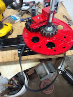
Dual Weight PIE Bench Test & Making the Drive Jackshaft Dual Weights (Maybe I'll take a pic without all of my workbench clutter in the background someday) Two days ago, as I was finishing up for the day, I decided to put both new weights on a single flexplate assembly at the same time. I really did this as a way to see the action and make observations of any interference between them. I was pleasantly surprised when the interaction appeared to be complimentary in nature. I was so pleased with the interaction that I decided to “spin” it up with the cordless drill. The amount of power being transmitted to the bench was remarkable, and because the flexplate was “balanced” out with the second planet assembly, I was able to run it at a somewhat higher speed without further modification. I observed the weights each contacting a stop (one inner, one outer) at virtually the same time and producing complimentary pulses. I was so pleased that I immediately cobbled together a way to

Vol. 2, Page 3, Preparing Parts for PIE 2.0, Second New Weight -Build and Test-

Image
Newest Weight Ready for Testing Building the revised PIE, version 2.0, is well under way. There are two weights are virtually ready for testing. The gears are looking as good as they ever will, and the base has been partially modified to accommodate the revisions in the configuration. I have decided that the drive system will be using #40 roller chain & sprockets. The sprockets and chain are available at a very reasonable price from surplussupply.com. It is too bad that they do not have spur gears to use for the sun & planet gears as well. Regardless, I am getting as much done as feasible while I wait for the sprockets arrive (I already have chain).   I am planning to use a jackshaft, of sorts, to drive the chain. The inexpensive and plentiful components already sourced and obtained will comprise a portion of the jackshaft assembly. I am having a custom shaft machined upon which to fasten the sprocket. A custom shaft would be unnecessary if the shaft, sprocket and availab

V2, Page 2- PIE 2.0, Problem with Physics, To-Do List, and A Personal Note

Image
First: The PIE 2.0 project has commenced.   As could be seen in the pictures contained in my last post, a new weight is being developed for PIE 2.0. I plan on using the same design for the planetary gear sets because I they are simple and robust. I was not sure about the flexplates, but since they are already prepared for the purpose, I will use them until a reason to change presents itself. Some parts are being reused (from the 4-wheel unit) and/or repurposed. There are still many questions to be answered and most of them need to be put on the work bench in order to find the answer. We know that computer models and all the advanced trigonometric formulas in the world are useless unless there is a way to put them to work. The differences between types of drives can be discussed, compared & argued but the proof is in the workshop. Sooooooo… I need to make something PERFECTLY clear. The fact is, this damn thing works ! Setting up for bench Testing Setting up for bench Testing  

Volume 2 (V2), Page 1, PIE 2.0 Begins

Image
Volume 2 (PIE2.0)… The rework of many unused parts that are left over from PIE1.0 has begun, along with some newly fabricated pieces for the new unit. Planning for this began about the same time that the first successful demo pulsed its way across multiple work benches. From the time that first unit moved on its own I have wanted to build a better unit, capable of higher RPMs and running a heavier pendulum weight. Digressing to, and remembering, the 1970s VHS video of Brandson Roy Thornson’s drive pushing a canoe around an Olympic sized swimming pool, that unit had 4 rotating discs (2 CW rotation, 2 CCW rotation) and each had a 5-pound pendulum weight. PIE 2.0 is going to start out with weights that are around 4.7-pounds. They will not be using any counter-rotating assemblies unless it is deemed absolutely necessary. Yet to be determined is to the number of rotating assemblies, the power source, and speed of rotation (RPMs). I have about 20 to 25 pictures of various parts, piec

Page 26, TEST DATA!!! Coming Up Next, PIE 2.0

Test data is coming in now. After a few hiccups in the testing procedures, the data is clearly indicating that the PIE is taking a small percentage of load off the test vehicle’s engine.   All percentage of engine load reduction readings are automatically averaged by the scan tool taking those readings. All readings used in this test phase taken by Matco Interrogator, which is the Matco branded OTC Pegisys scan tool. 1-mile test track with 20mph speed limit and 2 stop signs: 2% engine load reduction . Same 1-mile track with battery at 10.5 volts: 2% engine load reduction. 50/50 highway & city (light traffic) 55mph & 30mph limits respectfully: 3 % to 5% engine load reduction. Traffic variations causing engine load reduction variation These conditions were repeated over and over with solid repeating results. So it is official, PIE 1.0 is a success, testing reveals that it works as an add on hybrid system. I think that the most amazing revelation is that the PIE exerts

Page 25, Project Goal Added, To-Do List Updated

I have a very important goal added to the design phase of PIE 2.0. It is something that crossed my mind in the beginning but was not something that was as important as simply getting the drive to work. Now it seems more important than ever to stay with the true spirit of a “Grassroots Mechanic Movement”! Simply put, the PIE needs to be an engine that can be built by mechanics everywhere with average shop tools & equipment with a minimum budget . No needing a lathe, milling machine, shaper, dividing head, or other tools which are common in machine shops but not in the average mechanic’s workshop or garage. I do have most of these available to me but as I was getting ready to buy material and set up machinery to make parts, I asked myself “how many mechanics have this option available to them?”, and the answer was “damn few, that’s how many”. The common hand tools along with a welder, grinder, and chop saw are all the equipment required so far and it is my goal to keep it as

Page 24, On-Road Testing Now Underway

I am performing the on-road testing phase now. I will say that I am impressed so far, even without completing a recorded data set. It is truly amazing to feel the vehicle being pushed along using so very little power, while also decreasing the amount of throttle given to the engine because of the engine load decrease. The only change I have made to the PIE is the addition of a switch and relay to control the PIE from the driver’s seat. In the shop, I am preparing for PIE 2.0. I deliberated heavily about the planetary gear sets. I would like to replace them with machined gears which would run quieter and smoother, but I will stay with the simple fabricated gears for now. I already have parts made to fit the fabricated gears, so this will save the time and the expense of rebuilding some components. I seriously thought of upgrading everything, bearings, plates, gears, weights, etc. but cannot justify that at the present so it will have to wait for version 3.0 or higher.  I am, howev

Page 23, Thornson Book, Video & Patent

Because the PIE is so closely bound to the many years of dedicated work of Brandson Roy Thornson, I am providing some of the most  pertinent  info I have for anyone interested. I have uploaded copies of the book “Inertial Impulse Propulsion Engine of Brandson Roy Thornson”, the “Thornson Physics” full movie-length video, and the Thornson U.S. patent.  They are saved t o a Google Drive that I only use for sharing information.  Here are links to each of these works,.  Please note: The video's quality is rather poor at times. It was recovered from old VHS tape format which was degrading in storage. Also note: The book seems a bit disjointed, or out of order. This is exactly as it was published and delivered to me. The information in its pages is priceless and needs to be preserved. Video: https://drive.google.com/file/d/1rRlu5DZCNO3Pf6BgSCf_nFqG5ZHPJ4cD/view?usp=sharing Book: https://drive.google.com/file/d/198m-b8vt9I4S-U9W4NFpJQR-CavgQR5D/view?usp=sharing Patent: https://d

Page 22, Is This a Thornson Drive or PIE? Yes, It’s Both.

Is This a Thornson Drive or PIE? Yes, It’s Both.   I have started getting some comments stating that the PIE “is a Thornson drive”, so the question of whether this is a Thornson Drive, or a Pulsed Inertial Engine (PIE) is answered as “yes”. Let’s address the differences, and the similarities. I want to state for the record that the basis of this drive (or “engine”, as Roy Thornson called it) is the planetary gear design, including the planet weight, which was originated by Brandson “Roy” Thornson. I also want to state that I have carefully studied copies of original notes, some of which are signed by Roy Thornson. I originally studied these things to relate his discoveries to an earlier project of my own but decided I should put that design on hold to pursue this project. The most significant difference between the PIE and Roy’s drive has to do with the handling of the weight, and what Roy called inner & outer “planet traps”. That was designed to hold the weight until a spe

Page 21, A Resounding Successful Test Drive!!!

Image
May 13, 2020 The very first “real world” test drive/road test has been completed, successfully!!! This is a major milestone for the PIE. This first road test was done with no instrumentation installed in the subject vehicle, so there is no empirical data for the record. I also did not install a remote switch or camera. The next round of testing needs to include vehicle data recording instrumentation and the ability to turn the PIE on and off remotely from the cab. Conditions: Ambient temp; 40 deg. F. Subject vehicle; 2005 Chevrolet Colorado, 4WD, Crew Cab Power Source; 12v lead acid battery Connection; Alligator clip wires direct from motor to battery Mounting; Fastened to a wood pallet in truck bed, pushing on front of bed, tied down with strap Direction of Travel; Predominantly North/South with up to 3.5 miles of East/West Terrain: Paved highways with some hills with grades up to 5% & one gravel lane-way approx. 1000’ long Speed: City speeds/traffic 0-30 mph

Page 20, Prepping for Road Testing

Image
May 9, 2020, Prepping for Road Testing Preparations are under way to be ready and able to perform the next phase of operations, which is road testing. Since this will be tested in an open-air pick-up truck bed, several issues come to mind. First, unattended operation. Nobody will be in the back with it due to state laws prohibiting riding in the back of a truck. If timing does slip, or there is a mechanical failure there will be a significant time lag between the failure point and human intervention. (Note: Most testing facilities also prohibit open-air riders without expensive safety harnesses and specialized equipment) Second, the weather. The PIE needs to have some protection from inclement weather and from any debris that the wind could potentially deposit in the open gear mechanics of the PIE. Third, nosy people. This is potentially the trickiest part of the testing. At this early stage of testing, a bit of privacy would be advantageous. The public is invited to

Page 19, A New Video, Adjustments, & To-Do List

May 6, 2020, Adjustments Made, To Do List Update, & 3-Speed Running Video Work has kept me busy with little time to spend lunch hours working with the PIE, but I did take the time to do some timing adjustments. It seems strange to me that the setting is so different between the opposing spin plates & the synchronous spin plates. I have continued with timing adjustments being made for maximum thrust without the PIE on any wheels or rollers. It is reasonably easy to see torque & thrust when sitting on a bench or table since it will attempt to push the small bench in the forward direction, even to the point of tipping it up on two legs when thrusting. Perhaps the final settings will (once found & recorded) will help enhance other designs such as the opposing spin design originated to work in a zero gravity & zero atmosphere environment, time will tell. I did note that different timing settings were more effective at different rpm's. When running o

Page 18.5 - Announcing a YouTube Channel

Just an announcement, I have started uploading to a YouTube channel. The link is: https://www.youtube.com/channel/UCFTYcqNlDGnUHE8WZ0Cnj8A Stay tuned for content!