Posts

Showing posts with the label EZKL

Intro:

Date Written: April 3, 2020 Welcome to the Grassroots Mechanic Movement Blog:  All other posts (not this intro) follow the project's timeline. Most of the contents here are my personal notes & pictures, placed here as a record of my journey. It is not a written for anyone in particular.  Comments are encouraged, even if only to say that you were here. Thoughts, notes, or suggestions are welcome.  Some visitors will undoubtedly wish to tell me how foolish and impossible this is, please do not bother, as flaming and/or  non-constructive  criticism will not be well received here. I am B. I am a professional Auto Tech with more than 35 years in the automotive mechanical industry. I am currently a garage manager responsible for the maintenance & repair of more than 20 vehicles in the Northeastern U.S. "Rust Belt" and I am looking forward to retirement. I can be a grumpy old fart with little patience for closed-mindedness, so no apologies are of...

PIETECH P.4, Coming Soon, a PITECH Builders' Manual, Also Continuing the PIE 4.3's Progress

Image
  PIETECH Manual:  There has been a “Manual” in the works for a while now. It is coming together well and once it is completed it should be a valuable resource for anyone wanting to experiment with Inertial Propulsion without spending untold hours with trial and error testing and expensive components that may not be exactly what is necessary. I have several reasonably complete drafts sent out to other people familiar with this technology for their opinions and criticism. Below is a preview shot of the Cover and the Table of Contents as it is right now. I am hoping to have this available before the end of the year! PIETECH Manual Cover There is also a section within the manual that explains the mechanisms which create the driving force in greater detail than has ever been published, to the best of my knowledge. Color photos and detailed instructions means that little or no math is necessary to follow along, build a working PIE 1.0 or 2.0, and gain a better understanding of the ...

Volume 2 Page 15, PIE 4.0, The High Speed PIE:

Image
PIE 4.0 The latest incarnation of the PIE is kind of a step back to an earlier design as well as a step forward to push the limits of PIETECH possibilities.   I am using a single wheel (for now) with a much lighter weight, even lighter than the PIE 1.0 design. I am trying out a quiet gear set which uses a 14mm pitch timing belt as the teeth which is fastened to the same size (3.5") steel pulley as used on the PIE 1.0 & 2.0, and although it is quieter I am not sure if the teeth are robust enough to use as a spur gear. Initial testing of the PIE 4.0 is very encouraging, although there are some small issues arising from the increased speed which has currently been measured at just over 750 RPMs. The most serious issue has been the used motor I pulled off of the storage shelf. Although the 110 volt motor was marked as “Good” because it runs well without a load, it quickly overheats and shuts down when it is turning the PIE4.0. The other issue is the soft gear design which seem...

Comments about Comments, and Thank You

I have received a number of comments on YouTube, Bit Chute and by other means regarding the inefficiency of this design, and how other designs are soooo much more efficient and can produce these vast amounts of thrust, how this will never work and I am wasting my time chasing this dream. I have been pointed towards many fine inventor's works and have had private message conversations with some about some of these. Here is the deal: 1- I am going to pursue this to some sort of conclusion, it will either be successful or not.  2- There are those who want this stopped. 3- There are others who think there is a better way but have not built a prototype. 4- There are those who don't give a crap but like to make fun of other's efforts. 5- There is always "self doubt" when trudging through the swamp of the unknown. 6- Do not try to force your opinions on me and I will not try to force mine on you. 6- Tell me it can't be done and watch me go, but do not get in the way....

New Announcements, Global Collaboration, and "PIETECH Electric Propulsion":

  Announcement: Announcing "PIETECH Electric Propulsion": It has been a couple of weeks since my last post, but I do not want anyone to think I am not actively pursuing this quest for universal electric propulsion. The Grassroots Mechanic Movement continues the "Open Source" mission to see this technology advance and freely share information. The Grassroots Mechanic Movement is also in a well controlled growth period which will be branching out creating a somewhat separate entity which will be the "industrial development" branch known as "PIETECH Electric Propulsion" which still needs a logo. Everything here on  The Grassroots Mechanic Movement blog remains free and Open Source always, but PIETECH Electric Propulsion is going to allow the PIE technology to expand into the industrial mainstream as this still-infant technology grows and matures. Current Work: Currently I am continuing the R&D work necessary to advance the technology of the...

Volume 2, Page 14, Re-Phasing the PIE 2.0 and Ground-Test #2 - SUCCESS!!!:

Image
Re-phasing for Performance Since the PIE 2.0 did not perform as well as expected on the “self-propulsion” portion of testing, it was removed from the pallet for rework on the work bench. The phasing of the upper and lower wheels is the primary area to be reworked as the possible answer to its poor performance. The PIE 2.0 was not built for easy phase adjustments, so the rework included the removal of all planet gears and axles. The rework is a re-phase of the wheels from a 90-degree offset to a 0-degree offset. It would be much better to change the phase offset in smaller increments (say 10, 20 or even 40) but since this is the way already built into the design, this is how it is being done. Fast Forward a Couple of Days Later and “Ground Test #2”… That has done it! The re-phasing has made significant improvements in the quest for “self-propulsion”! It will now work its way across the garage floor under its own power with nothing driving the wheels! The upper planet gears and...

Vol 2, Page 13, Ground Testing

Image
  Post vehicle, wheeled, ground-testing. After a short pause caused by things in life that have required my undivided attention, I’m back & ready to get busy.   So, the on-road testing would be considered a success, and the “hybrid-assist” effect is undeniable. The “failures” encountered within that round of testing were due to the prototype building methods and materials. It is hard to justify the cost in time and materials for a more durable build when it is being taken apart and changed multiple times. Total cost of materials for a single planet gear, without the weight, is around $8 US. The cost of a machined, straight toothed, drilled hole center, spur gear of the same size is around $200 to $300 US. In that light, the component failures are an acceptable offset to the cost differential. Now we move forward with further testing of the PIE 2.0 while still getting ready to build a next version.  **************************************************************...

Vol 2, Page 12, Successful Testing and Prototype Component Failures

Image
PIE 2.0 All Pretty -- Before Being Worked Hard, Out in the Real World  I find that it has been tough to get busy and simply do what needs to be done lately. The PIE 2.0 has had to take a “back seat” to far more important family business, but I finally did get some time to finish up some “real world” testing at a reasonable speed of 55 MPH (88 KPH). It is not an easy thing to find a “flat” stretch of highway in the Northeastern United States (about 350 miles inland), so I have made do with a straight stretch with only some small rolling hills and with an estimated elevation rise from start to finish of approximately 15-20 feet (not verified with altimeter). As before, measurements are taken and only considered valid if measured values are repetitively similar. I was able to bring the PIE 2.0 up to slightly over 120 RPMs and test before it broke this last time and left a weight laying in the truck bed. So, here is a simplified recap of test results obtained on this test roadw...

Vol 2, Page 11 - Getting Back To Work & Another Approach to Planetary Gears -FAILURE UPDATE AT END OF POST-

Image
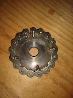
Next Gen Test Gear After some unexpected personal business (death in the family) to be attended to, I am excited to pick up where I left off with the PIE 2.0. I had to remove the test rig from the test vehicle in order to transport several loads of “rubbish” from a deceased family member’s apartment to be delivered to either a charity donation center or a dumpster for disposal. The Pie 2.0 is fastened back into the test vehicle, testing routs are mapped out for highway speed testing, and I am ready to start recording data. As seen in the photo above, I have also been working on an improved method of obtaining and making planetary gears. The latest idea on this front is an inside-out chain drive/sprocket assembly. I don’t think that it is a long-term production solution, but it seems to present a reasonably inexpensive alternative to making gears from scratch. The nice people at www.RollerChain4less.com (Nitro Power Products, LLC) have 17-tooth idler sprockets wi...

Vol 2, Page 10, Preliminary Test Results

Image
The PIE 2.0 is running much better now, and although it was not without frustration, I was finally able to make some test runs. I did have to make some repairs to the lower sun gear and I also corrected the crooked outer stop. One of the teeth on the lower sun gear broke off and when that happened the lower wheel started "jumping timing" like crazy. When the failure(s) happened, the timing got pushed to the 11 o’clock position and that is a bit too “retarded” or “late”, the planetary alignment position (I like that terminology) should be a bit earlier at about 10 o’clock. This late timing is very evident in the PIE’s upper framework, when running at just over 100 RPMs the upper frame deflects to the right which tells me I am losing forward propulsion power. I am fortunate enough to be able to see the upper part of the pie in my rear view mirror while driving so I was able to visually see that the timing was off. I took a short video of the sideways movement to demonstrate...

Vol 2, Page 9, Testing the PIE 2.0, and My Patience

Image
Well it works, but as with any new design there are issues. I have put around 19 miles on it and it really does seem to work well, when it will keep running. First and foremost is the locking up problem. The little springs did a reasonably good job of stopping the lockup on start-up, unless I started it at a bit of a higher speed. High speed start-up would overpower the springs and locking was still an issue. Then came the locking problem while driving. Every time I might hit a bump, or tap the brakes, it would lock up. So, I took the weights off, cut the metal tab off for the outer stops, and welded stops onto the planet gears. One corner of each weight then had to be trimmed so it would not hit the new stops and viola, no more locking. I did get one of the stops a bit crooked, but I will fix that next week. Second was the drill motor kept cutting out. Apparently, there is a bad spot in the variable speed trigger, and (of course) I found it. With the new stops came a bit of a smooth...

Vol 2, Page 8, The PIE 2.0 is Ready for Testing

Image
The PIE 2.0 is basically ready for real world testing. The PIE is fastened to a pallet and is being driven by the cordless drill used to test it. I made a bracket for the drill and "gutted" an inoperative battery pack so I could connect wires easily. This allows me to power it from the vehicle's electrical system or a 12V battery so that a simple on/off control is accessible to the driver. PIE 2.0 Ready to come off Work Bench    The Power for the PIE 2.0, and the Bracket for the Drill I do still need a weather cover as it will be tested in the same pickup truck as the PIE 1.0 was, but that is the simple part of the whole project. I will be posting all findings here on the blog and also on MeWe ( www.mewe.com/i/bryanstclair ). I want to reaffirm the intent of the Grassroots Mechanic Movement (GMM) to freely distribute and promote the "reactionless" propulsion technology of the Pulsed Inertial Engine (PIE). I do not advertise the Grassroots Mechanic Movement, and ...

Vol. 2 Page 7, PIE 2.0 Major Update,

Image
Building Upward & Using Torsion Springs I have repeatedly said that I would make this project 100% open source, I am keeping my word and even though I don’t have it ready to run yet, I am posting a reasonably major update now. I have not posted any real updates as to the status of the PIE 2.0 build in the last few days, so here is what I’m up to. The PIE 2.0 is progressing very well so far. I had a problem with the weights “jamming” on start up because I am using the planet gear axles as the outer stops. This seems to be alleviated by using very weak torsion springs to push the weights out of the position that jams the rotation. The springs add very little to the force of the weights swinging outward and should pose no significant change to operation. I will include more info about the springs if anyone requests it, and if there is someone following this who is also building a PIE 2.0, I can get these springs for you if you let me know. The significant portion of this update ...

Vol 2, Page 6, The PIE 2.0 Is Coming Together

The PIE 2.0 build continues as the new chain drive works very well and the unit is now being assembled on its own base so that it will be mobile. It is a notable observation that the PIE 2.0 pulled the work bench out of place on multiple occasions during individual component testing. Bench Testing It is easy to see the rpm variation potential now that slip is eliminated between the drill and the PIE’s wheel. For testing purposes, I have braced the drill with a piece of metal so it wouldn’t keep pulling it back and causing speed variations since I was not holding it steady enough. As I continue the build, I still have not decided on a motor to power it. I do not want to commit to any particular motor design or speed, before doing some initial testing. There is still more work to do before I get to that point, at which time I will post those results here as well. I am certain of is that if the PIE 2.0 becomes much more powerful, the whole unit will need a redesign so that it does n...

Vol 2, Page 5, Sprockets & Roller Chain Drive

Image
Bench Testing Chain Drive with Drill as Power Source I finally got my sprockets for the chain drive! They are surplus so there are nicks and dings, but nothing a file won’t easily fix. They have an “unfinished” one-inch (25 mm) hole, that puts the hole slightly undersized, but that actually worked out in my favor for use on the jack shaft as it made for a nice press fit on the 1” section of shaft. I then welded the sprocket into place on the shaft to make it a permanent install. I used a plasma cutter to open the 1” holes up on the sprockets being used on the wheels, that way there is no need for spacers to mount them on the axles. Cutting the hole open like that is ugly, but I don't really care, as it cannot be seen once it is installed. I put it together enough to see the chain drive work with a cordless drill running it up to approximately 1500 RPMs. I still need the parts bolted to the plank base so that nothing can shift position with the weights installed. I believe...

Vol 2, Page 4, Dual Weight PIE Bench Test & Making the Drive Jackshaft

Image
Dual Weight PIE Bench Test & Making the Drive Jackshaft Dual Weights (Maybe I'll take a pic without all of my workbench clutter in the background someday) Two days ago, as I was finishing up for the day, I decided to put both new weights on a single flexplate assembly at the same time. I really did this as a way to see the action and make observations of any interference between them. I was pleasantly surprised when the interaction appeared to be complimentary in nature. I was so pleased with the interaction that I decided to “spin” it up with the cordless drill. The amount of power being transmitted to the bench was remarkable, and because the flexplate was “balanced” out with the second planet assembly, I was able to run it at a somewhat higher speed without further modification. I observed the weights each contacting a stop (one inner, one outer) at virtually the same time and producing complimentary pulses. I was so pleased that I immediately cobbled together a way to...

Vol. 2, Page 3, Preparing Parts for PIE 2.0, Second New Weight -Build and Test-

Image
Newest Weight Ready for Testing Building the revised PIE, version 2.0, is well under way. There are two weights are virtually ready for testing. The gears are looking as good as they ever will, and the base has been partially modified to accommodate the revisions in the configuration. I have decided that the drive system will be using #40 roller chain & sprockets. The sprockets and chain are available at a very reasonable price from surplussupply.com. It is too bad that they do not have spur gears to use for the sun & planet gears as well. Regardless, I am getting as much done as feasible while I wait for the sprockets arrive (I already have chain).   I am planning to use a jackshaft, of sorts, to drive the chain. The inexpensive and plentiful components already sourced and obtained will comprise a portion of the jackshaft assembly. I am having a custom shaft machined upon which to fasten the sprocket. A custom shaft would be unnecessary if the shaft, sprocket and ava...