Posts

Showing posts from April, 2020

Page 18, Little Red Wagon & Modifications Made

Image
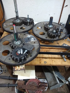
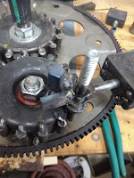
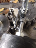
April 30, 2020 I decided to put the whole unit on a small (rather wobbly) little red wagon to see if it would pull it around or at least if it would make it easier to push it up an incline. The wagon is far too wobbly to be used effectively but it did push it around my shop floor. I also see the absolute necessity of making the sun gear timing adjustment lock securely. As I was testing, one of them suddenly drifted right, to the point where it tried to tip the red wagon over. It was time to tear it down and rebuild the gear adjustment locks…And so I did... Here is where I ended up.   I have realized that the only "good" video I have put here is of the first functional demo unit. Here is a video of the it with all of the latest modifications (listed below). I did not have it on wheels in this video, it is very difficult to keep it on the bench if there is anything under it that it will roll on.   Modifications Made: Switched wires on motor

Page 17, T-belt Timing for Maximum Thrust

April 29, 2020 ( T-belt Timing) Now that the T-belt is installed & working with two flexplates, the question of how to time the two flexplates is at hand. Since there is negligible backward push, it is all about "maximizing" and “smoothing” the forward thrust. Observations made are as follows: 1- The closer the two flexplates are timed together, the forward push increases but so does the “pulsation” effect of the drive. 2- With the timing set at 180 degrees, the pulsation is very low but so is the forward thrust. 90 degrees does work, but I am not very pleased with the forward thrust & it almost seems that the two halves are fighting one another. 3- Setting the timing to approximately 30 degrees apart (12 & 1 o’clock positions) is very promising. 4- Although testing is necessary to state this conclusively, bringing the clock positioning closer together increases the thrust power more than a simple ratio would explain. If it were a

Page 16, Timing Chain or Timing Belt?

Image
April 28, 2020 (To Chain or To Belt, That Is The Question) Since identifying the need to eliminate the belt-slip/speed-variation problem and because I want two flexplate assemblies synchronized and both turning CW, either a roller chain or a toothed belt has  to be used. The dilemma was in deciding which would be better. I really like roller chains because they are a very forgiving utilitarian design which will work in the harshest conditions, even if not perfectly tight or aligned. The downside is that they are heavy, noisy & require regular lubrication. I like toothed belts (t-belts) because they eliminate the downsides of a roller chain, i.e. they are light, quiet and do not require lubrication. The t-belt downside is that they are rather “finicky”, they need to be well aligned, tight and clean.   After much consideration, I am installing a  toothed  timing belt for this prototype. If it proves to be too troublesome it will be replaced with roller chain &am

Page 15, Stability vs. Instability & Revised "To Do" List

Image
April 21, 2020 The working phrase of the day is: “There is a necessary dynamic stability in the build as well as a necessary dynamic instability. An Excess of either is intolerable”. I learned a few things today. Some of these things I already knew, but was not giving proper consideration, others that have formed new ideas and will be added to my list of things needing exploration. Today I made it into a 3-wheeler, two flexplates turning clockwise (CW) & one turning counterclockwise (CCW). The two CW plates are timed exactly together while the CCW is still 90 degrees behind them. The amount of forward push effectively doubled, coming from the pair of CW plates. And the single CCW quite effectively extends the time that the machine pushes between “pauses”. This tells me that configuration is of the upmost importance! I learned quite a bit about this machine’s timing & it seems that it can be correlated to a spark ignition type IC engine’s timing (cam, tach, dwe

Page 14, Phase 2 - Outer Stops Cont...

Image
April 14, 2020 The revised outer stop (os2) seems to be the most effective, however, it should be noted that it also puts the heaviest strain on the gears. The strain tends to change the timing of the sun gear(s). I am thinking that I should fasten the sun gear(s) to the axle shafts and change the axle shaft mountings to enable “on the fly” timing adjustments. I have also added the stop tab (which contacts os2) to one of the 1” square weights. The result was a dramatic improvement over the original trials with that weight and I also had to add an extra stop tab to the 1” square to keep it from “backfiring” or spinning itself around to the wrong side of os2. This all showed me that the os2 is really absorbing a tremendous amount of torque from the weight, and as the timing of the sun, planet and weight are becoming much more critical it is also having a harder time maintaining adjustment. Note: After multiple, successful tests the forward thrust would suddenly be very

Page 13, Phase 2 - Outer Stop

Image
April 8, 2020 The outer weight stop is the device that stops the outer weight from swinging past the apex position of the planet gear. It stops the swing, absorbing the energy being imparted by the inertia of the weight, transferring that energy into forward motion and allowing the weight to stay at apex until it returns to the center of the sun gear and contacts the inner stop. The inner stop holds the weight until it is in position to be swung outward/forward where it contacts the outer stop again. This illustrates how important the stops are and it begins to illustrate the stress imparted upon the gear teeth and the locks that keep the sun gears timed properly. The outer stop seems to be where a large part of the stress is, so that is where I am concentrating my refinement efforts. I have now tried several stops, and the 2 most successful will be called os1 and os2. Os1 is fastened directly to the planet gear and extends outward toward the weight where id stops the s

Page 12, Phase 2, Refinement of the Drive & "Successful Failures"

April 7, 2020 The refining of this drive system requires intimate knowledge of what does NOT work! There have been many tries & fails throughout multiple projects on my path to this point. It is very difficult to remain optimistic through multiple obstacles, many times where I would have to avoid the deep, sucking hole of self-doubt & even depression.   Every time something that I thought should work, but didn’t, I HAD to see it as a “Successful Failure”. That means there is no such thing as a failure, only the opportunity to learn. That is something which made me a great diagnostician in the auto repair industry for so many years (or, so I am told). Fortunately, that makes the successful tests, changes & experiments that much more gratifying. Now begins the refinement of this reactionless drive into a final product that can be a useful addition to mankind’s goals of energy independence as well as cheap & efficient propulsion for virtually all typ

Page 11, Recap & "State of the Project"

To recap where this all stands at this point in its development: 1-       Two matching 13” gears (automotive flexplates) are attached to 3” smooth idler pullies which are mounted to a beam so that the teeth are engaged between them ant they can spin freely on the idler pully bearings. These flexplate assemblies will be referred to as “Main Gears”. The axles that the Main Gear s rotate on are 5/8” threaded rod, and they need to extend through the Main Gears enough to be used as inner planet traps (6” to 10”). A 3 or 4 inch long piece of 5/8” heater hose is slid onto each Main Gear axle for the weight to contact. 2-       A 3” flat pully is mounted to a used Honda windshield wiper motor to drive the assembly via a serpentine type automotive belt. 3-       Four 3-1/2” flat idler pullies are used for the sun & planet gears. Short (approx. 1”) pieces of 3/8” diameter steel rod is welded to the OD of the pullies, transforming them into coarse toothed spur gears. One “tooth”

Page 10, Back to v2 Weights With Improved Stops & Longer Pivot Bolts

Image
April 3, 2020 I went back to V2 weights, removed the magnet from both and welded a “bump” onto each of the pivoting bolts so that they contact the stops firmly when the weights are in their fully extended positions. After retiming the sun & planet gears to use this setup, I am reasonably pleased with the amount of thrust.

Page 9, Square Bar Weights Not Beneficial

April 2, 2020 I am not so sure that the new pendulum weights are going to work out. I have both weights installed & I have replaced their pivot bolts with somewhat longer ones so I can get a full nut on them. I also had to reinforce the stops because they were getting bent. Since I have them set 90 degrees out of phase there is no way for the weights to contact one another, so I am using both planet gears without the raised pivot. Forward thrust (with V3 weights) is present but is not as good as I was hoping. I may go back to the V2 weights.