Posts

PIETECH V.1, P. 3: PIE 4.3 has a Brand-New Cart, 1st "On-Wheels" Test

Image
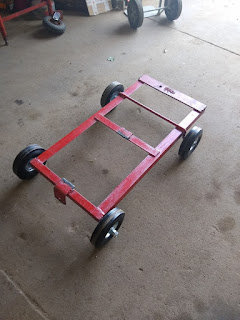
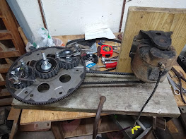
 I am now actively conducting thrust tests on the PIE 4.3 with positive results.  Since it certainly appears to have a lot of propulsive force in bench tests and is rather unruly on the bench, it seems that a heavy and sturdy cart should be used.  I have modified a steel cart, which I had originally built for an entirely different purpose, just to be the new PIE 4.3’s cart complete with solid solid tires and ball bearing wheels.   New Cart With New Wheels It took several runs at nearly full speed to properly adjust the sun gear for forward thrust without pulling to one side or the other. During those test runs, there was enough force to move the cart forward and slide the wheels sideways approximately 10 inches.   Mounting The PIE 4.3 To The New Cart During those test runs, one outer stop broke and the excessive lash on one of the planet gears caused it to skip timing, but even though weaknesses were obvious the overall test was successful. PIE 4.3 On Its Wh...

PIETECH V.1, P. 2: Redesigned Sun Gear Makes This Model The “PIE 4.3”:

Image
  Inverted Chain Sun Gear I am really pleased with the raw power that the PIE 4.0 exhibits. This power is still quite wild and unrefined, but it is impressive, nonetheless. I was happy with the inverted chain design, but I quickly saw some issues that would give me trouble keeping the PIE running. Mainly the width of the chain is too narrow to allow for wheel run-out and axle deviations. The main wheel is expected to deflect some and I am not using a precision sun gear axle so I have no realistic expectation of it being perfectly straight. Narrow Chain/Gear Mating Area Now the sun gear has now been redesigned/improved. It still functions as an inverted chain but rather than roller chain, 8mm (5/16”) rods are used. The new sun gear width is 30mm (1-3/16”) so there is plenty of room to change designs. Redesigned Sun Gear The new sun gear is made from two #40-26 tooth sprockets with the teeth cut nearly off and 8mm (5/16”) rods welded into the remaining tooth divots. A piece of ...

PIETECH Volume 1, page 1: PIE 4.0 and PIE 2.0 Thrust Stall Test Results

Image
      PIETECH As we open a new chapter in the PIE project previous chapters are not closed, instead they continue as the earliest pioneering efforts put forth leading to PIETECH and will undergo more extensive power in/out ratio testing for scientific purposes. The PIE 1.0 & 2.0 are also the necessary “trainers” to teach the concepts of PIETECH, and actual building plans are forthcoming within the next few months! Update added: The PIE 2.0 requires just over 30 oz of thrust to self-propel as seen in the earlier posted video. Another test was run, using weights placed in front of the PIE 2.0. The weights were added until it would not move them, then backed off until movement was just apparent. Then a digital scale was used to push the whole rig forward in order to determine maximum thrust (stall method). This test was repeated a total of 8 times with identical results. Maximum thrust is now calculated at 230 oz which is 14.375 lbs or 6.52 kg. Bryan- PIE 3.0 i...

Volume 2 Page 15, PIE 4.0, The High Speed PIE:

Image
PIE 4.0 The latest incarnation of the PIE is kind of a step back to an earlier design as well as a step forward to push the limits of PIETECH possibilities.   I am using a single wheel (for now) with a much lighter weight, even lighter than the PIE 1.0 design. I am trying out a quiet gear set which uses a 14mm pitch timing belt as the teeth which is fastened to the same size (3.5") steel pulley as used on the PIE 1.0 & 2.0, and although it is quieter I am not sure if the teeth are robust enough to use as a spur gear. Initial testing of the PIE 4.0 is very encouraging, although there are some small issues arising from the increased speed which has currently been measured at just over 750 RPMs. The most serious issue has been the used motor I pulled off of the storage shelf. Although the 110 volt motor was marked as “Good” because it runs well without a load, it quickly overheats and shuts down when it is turning the PIE4.0. The other issue is the soft gear design which seem...

Comments about Comments, and Thank You

I have received a number of comments on YouTube, Bit Chute and by other means regarding the inefficiency of this design, and how other designs are soooo much more efficient and can produce these vast amounts of thrust, how this will never work and I am wasting my time chasing this dream. I have been pointed towards many fine inventor's works and have had private message conversations with some about some of these. Here is the deal: 1- I am going to pursue this to some sort of conclusion, it will either be successful or not.  2- There are those who want this stopped. 3- There are others who think there is a better way but have not built a prototype. 4- There are those who don't give a crap but like to make fun of other's efforts. 5- There is always "self doubt" when trudging through the swamp of the unknown. 6- Do not try to force your opinions on me and I will not try to force mine on you. 6- Tell me it can't be done and watch me go, but do not get in the way....

New Announcements, Global Collaboration, and "PIETECH Electric Propulsion":

  Announcement: Announcing "PIETECH Electric Propulsion": It has been a couple of weeks since my last post, but I do not want anyone to think I am not actively pursuing this quest for universal electric propulsion. The Grassroots Mechanic Movement continues the "Open Source" mission to see this technology advance and freely share information. The Grassroots Mechanic Movement is also in a well controlled growth period which will be branching out creating a somewhat separate entity which will be the "industrial development" branch known as "PIETECH Electric Propulsion" which still needs a logo. Everything here on  The Grassroots Mechanic Movement blog remains free and Open Source always, but PIETECH Electric Propulsion is going to allow the PIE technology to expand into the industrial mainstream as this still-infant technology grows and matures. Current Work: Currently I am continuing the R&D work necessary to advance the technology of the...

Volume 2, Page 14, Re-Phasing the PIE 2.0 and Ground-Test #2 - SUCCESS!!!:

Image
Re-phasing for Performance Since the PIE 2.0 did not perform as well as expected on the “self-propulsion” portion of testing, it was removed from the pallet for rework on the work bench. The phasing of the upper and lower wheels is the primary area to be reworked as the possible answer to its poor performance. The PIE 2.0 was not built for easy phase adjustments, so the rework included the removal of all planet gears and axles. The rework is a re-phase of the wheels from a 90-degree offset to a 0-degree offset. It would be much better to change the phase offset in smaller increments (say 10, 20 or even 40) but since this is the way already built into the design, this is how it is being done. Fast Forward a Couple of Days Later and “Ground Test #2”… That has done it! The re-phasing has made significant improvements in the quest for “self-propulsion”! It will now work its way across the garage floor under its own power with nothing driving the wheels! The upper planet gears and...