Vol 2, Page 10, Preliminary Test Results
The PIE 2.0 is running much better now, and although it was
not without frustration, I was finally able to make some test runs.
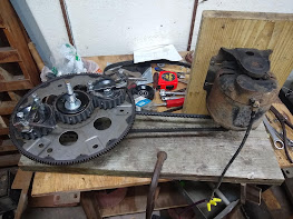
I did have to make some repairs to the lower sun gear and I
also corrected the crooked outer stop. One of the teeth on the lower sun gear broke
off and when that happened the lower wheel started "jumping timing" like crazy.
When the failure(s) happened, the timing got pushed to the 11 o’clock position and that is a bit too “retarded” or “late”, the planetary alignment position (I like that terminology) should be a bit earlier at about 10 o’clock. This late timing is very evident in the PIE’s upper framework, when running at just over 100 RPMs the upper frame deflects to the right which tells me I am losing forward propulsion power.
I am fortunate enough to be able to see the upper part of the pie in my rear view mirror while driving so I was able to visually see that the timing was off.
I took a short video of the sideways movement to demonstrate this to anyone building a PIE, I will show it here but I probably won’t post it on YouTube or Bitchute since it falls under the heading of a builder’s note but here it is.
During testing, I did not have the tools with me to adjust the timing
(won’t make that mistake again - I hope) so the results listed below were obtained with
incorrect timing.
Testing:
To eliminate variations in atmospheric and fuel conditions, all comparative tests are run consecutively.
Test Track: 1.2 miles with a 20-mph speed limit (during
business hours) around a nearly abandoned shopping mall with 2 stop signs.
The Scanner used to collect the data is a Matco Determinator, which is the Matco branded OTC Pegisys scan tool system, and the test vehicle is a 2005 Chevrolet Colorado Z85 crew cab pick up truck with a 3.5 liter engine and automatic transmission.
Multiple passes were made both with and without assistance
while monitoring vehicle speed and engine load on graphing scales with a
running average counter. There were some anomalous results obtained that showed
both better and worse results, so they were “thrown out” and only the repeatable
results were used to obtain that which is shown below.
Average speed measurement during all test runs was
maintained at 17 to 18 mph.
Engine load average without PIE assist.
- 40%
Engine load average with PIE assist. – 36%
Total gain with PIE 2.0 was a 4% reduction in engine load.
This “should” improve with the timing correction; results will be posted here
and on MeWe.


Comments
Post a Comment