Page 11, Recap & "State of the Project"
To recap where this all stands at this point in its
development:
1-
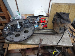
Two matching 13” gears (automotive flexplates)
are attached to 3” smooth idler pullies which are mounted to a beam so that the
teeth are engaged between them ant they can spin freely on the idler pully
bearings. These flexplate assemblies will be referred to as “Main Gears”.
The axles that the Main
Gears rotate on are 5/8” threaded rod, and they need to extend through the
Main Gears enough to be used as inner planet traps (6” to 10”). A 3 or 4 inch
long piece of 5/8” heater hose is slid onto each Main Gear axle for the weight
to contact.
2-
A 3” flat pully is mounted to a used Honda
windshield wiper motor to drive the assembly via a serpentine type automotive
belt.
3-
Four 3-1/2” flat idler pullies are used for the
sun & planet gears. Short (approx. 1”) pieces of 3/8” diameter steel rod is
welded to the OD of the pullies, transforming them into coarse toothed spur
gears. One “tooth” on each gear is made from a 3” long bolt (3/8” coarse
thread) to act as both a tooth and the pendulum weight pivot. These pivot bolts
have the hex head removed.
4-
A pendulum weight is attached to the pivot bolts
via a steel bushing (1/4” water pipe cut to length and drilled out with a 3/8”
drill) welded to the hex head of a 3/8” x 2” bolt. The weights are fabricated
from three steel squares (2” x 2” x 3/8”) placed together and welded. A hole is
drilled & tapped in the center on one side to accommodate the bolt. A lock
nut is threaded onto the bolt and then the weight is threaded on. Once in
position, the lock nut is tightened against the weight block to maintain its
position with the pivot bushing. The overall length of the pendulum assembly is
approximately 4-1/8” and the length from the center of the pivot is
approximately 3-3/4”.
5-
“Outer Plant Traps”… That is what Roy Thornson
called them, are restraints for the pendulum weights. Roy’s logs & patent
documents, call for an external restraint to catch (or trap) the weight after
it has left the inner trap and then release it at the correct time to allow the
weight to swing outward with a snapping motion. I have experimented with
different designs and for this incarnation of this machine it is unnecessary.
What IS ABSOLUTELY necessary is the Planet
gear mounted stop!!! It functions to keep the pendulum weight from swinging too
far when it is coming off the inner trap and it is an essential component that
“catches or stops the weight when it is swinging outward.
This is very important, the stop and the
weight MUST come together when the weight is the farthest from the planet
gear’s axle! Without this, much of the functionality is lost!
6-
Timing is critical! There is the Main Gear
timing vs the planetary gear timing. Originally the Main Gears were timed
together (because the “push” is not perfectly straight) so that one would
counter the other’s sideways push. We aren’t building this for use in space at
this time, so, this is absolutely not necessary!!! By offsetting the timing by
approximately 90 degrees the pulsation effect is reduced and thrust is
increased.
Timing on the sun & planet set is quite
critical and is set by placing the gears into a position where the planet’s
axle, the weight’s pivot bolt, and the Main Gear axle are in alignment and that
alignment (if using a straight edge) is approximately 45 degrees BEFORE top
dead center (when the alignment would point straight forward). There have been
incarnations of this build where that has not been the case but that was much
different.
7-
The speed of rotation (RPM) is an integral part
of the unit’s operation and the lengths, sizes, weights, and timing are a
choreographed “dance” which requires the speed to remain constant in order to
achieve & maintain flow. Different motors, battery voltages, drag
coefficients, etc. can & will affect the RPM and may require slight timing
changes to compensate.
Whew… That’s quite a recap… It sure didn’t
SEEM that --- um, “involved”…

Comments
Post a Comment